Since the emergence of methods for preparing diamonds using CVD in the 1980s, research on this diamond preparation method has been ongoing and in-depth. With the development of modern CVD diamond preparation technology, various CVD methods have been developed. The main methods for CVD diamond preparation include Hot Filament Chemical Vapor Deposition (HFCVD), Combustion Flame Chemical Vapor Deposition (CFCVD), Direct Current Plasma Jet Chemical Vapor Deposition (DCPCVD), and Microwave Plasma Chemical Vapor Deposition (MPCVD). This article briefly introduces the structures and characteristics of these deposition devices.
- Direct Current Arc Plasma Jet Method Device
To fully utilize the excellent physicochemical properties of diamonds and facilitate their application in high-tech fields, a surge in research on diamond films has been initiated. Hot filament CVD equipment is relatively simple and can grow diamond films over large areas; however, it has a low degree of gas excitation and can contaminate the diamond film, making it suitable for preparing tool-grade diamond films that have lower quality requirements and are cost-sensitive.
Microwave CVD devices do not have internal electrodes, effectively avoiding electrode discharge contamination. They also have a wide deposition pressure range, high electron density in the plasma, and a large concentration of atomic hydrogen, allowing for the growth of high-quality diamond films. However, their deposition rate is lower, and they require high power control, making large-area deposition of diamond films challenging. Diamond films prepared using Direct Current Plasma Jet CVD technology have high quality, large growth areas, and high deposition rates, making it one of the best choices for the industrial application of diamond films.

Figure 1: Schematic Diagram of the Direct Current Arc Plasma Jet Method Device
The device mainly consists of a power system, a water cooling system, a vacuum system, and a plasma torch, among other structures. A direct current arc discharge is formed between the rod-shaped cathode and the cylindrical anode, generating high temperatures that ionize working gases such as Ar, H2, and CH4. Under the influence of the gas field and electromagnetic field, these gases are ejected at high speeds and ultimately deposit diamond films on the substrate. The high energy of the plasma and a series of reactions occurring on the substrate allow carbon atoms in methane to bond and form polycrystalline diamond. Compared with other diamond film deposition techniques, the direct current arc jet CVD technology has extremely unique advantages, such as high plasma density, high ionization degree, high deposition rate (up to 900 µm/h), good diamond quality, and large deposition area. It is particularly suitable for the preparation of large-sized high thermal conductivity diamond film heat spreaders.
Li Chengming and others have researched and concluded that the current direction of diamond synthesis using direct current jet plasma focuses on producing larger and higher-quality diamonds. Considering the excellent application prospects of diamonds in precision machining, jewelry, optical windows, electronic devices, and other fields, direct current jet plasma is also used for the deposition of diamond single crystals and is about to enter the industrialization stage. With the further development of diamond preparation technology and the continuous reduction of production costs, its application scope and potential market will rapidly expand. The research on CVD diamond films has entered the stage of artificial industrial application, and after the steel era and single crystal silicon, humanity will usher in a more brilliant diamond era.
Source: Diamonds and Abrasives Engineering, 2018.1: 16--27. Recent Advances in the Research of Diamond Self-Supporting Films Prepared by Direct Current Arc Plasma Jet Method.
- Research on the Preparation of Diamond Films by the Constrained Hot Filament CVD Method
The hot filament CVD method has advantages such as simple equipment and the capability for large-area deposition. However, its low growth rate and high costs still limit its widespread application. There are two main methods to improve the deposition rate during the preparation of diamond films using the hot filament CVD method: applying bias voltage or radio frequency assistance, or adding auxiliary gases. The traditional deposition rate of diamond films using the hot filament CVD method is 0.9–2.0 µm/h. By applying bias voltage or radio frequency, the energy of electrons can be increased, the collision probability can be enhanced, and the plasma density can be increased to achieve the desired deposition rate. This technology has promising applications in advanced radar and telecommunications systems, ultra-efficient hybrid vehicles, electronic devices in extreme environments, and next-generation aerospace electronic devices.
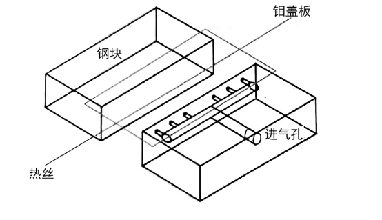
Figure 2: Schematic of the Constrained Space Deposition Model for Hot Filament CVD
The self-made constrained space device confines the hot filament and reaction gases within a narrow slit space, as shown in Figure 2. Two steel blocks of equal height are placed parallel to the substrate stage as constraint walls. The upper ends of the constraint walls are capped with high melting point Mo plates (melting point 2622 ± 10 °C), leaving a rectangular slit with dimensions of 8 cm in length, 3 cm in width, and 2.1 cm in height, open on both sides. The hot filament passes through the slit, with the substrate positioned directly below it. The reaction gas is introduced into the constrained space through sidewall inlets using a porous gas inlet method to ensure uniform gas flow distribution.
The constrained deposition method can effectively improve the growth rate. The reasons for this, according to Dai Kai and others, can be explained from three perspectives:
Energy Concentration: This includes both the energy concentration of the hot filament and the forced flow energy of the gas. During the deposition of diamonds using the hot filament CVD method, the high-temperature filament provides almost all the energy required for the deposition reactions. In traditional methods, the reaction space is relatively large, leading to significant waste of the filament's energy through radiation and thermal conduction. In contrast, the constrained method effectively concentrates the filament's energy under the same power conditions. Moreover, the introduction of reaction gases into a smaller slit reaction zone enhances the macroscopic forced flow, making the gas flow state more active and complex, increasing the collision frequency between the gas and the filament, thus enhancing excitation and cracking. The transport of reactive gas species becomes more efficient; conversely, the gas flow state in traditional methods is stable laminar flow, resulting in relatively low gas cracking and transport efficiency.
Concentration of Reaction Gases: Compared with traditional methods, the gases entering the slit are directly delivered to the effective cracking region of the filament, making the reaction gas more concentrated. Under the condition of energy concentration of the filament, more effective reactive particles can be excited and cracked.
Turbulent Effects of Gases in the Slit: Compared to traditional methods, the volume of the slit-constrained space is reduced, and the gases entering the slit undergo more significant forced flow due to the blocking and collision effects of the constraint walls, the heating expansion effect of the filament, and the suction effect of the vacuum pump. This results in the formation of complex active turbulence within the slit. The swirling turbulent state of the gas leads to repeated collisions with the filament, enhancing cracking and yielding higher particle densities and energy levels. Additionally, the higher frequency of collisions with the substrate reduces the boundary layer on the substrate surface, ensuring better deposition effects. In unconstrained deposition methods, gas excitation and transport of active particles are less efficient.
Source: Dai Kai, Research on the Preparation of Diamond Films by Constrained Hot Filament CVD Method, Diamonds and Abrasives Engineering, 2018.4: 1--5.
- Diversity of MPCVD Device Structures
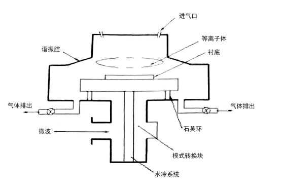
The advantages of microwave plasma chemical vapor deposition (MPCVD) lie in the fact that the plasma energy is maintained by microwave energy, eliminating the need for metal electrodes during the discharge process, thus avoiding contamination that can occur with other CVD deposition methods due to the use of metal electrodes. Furthermore, the gas discharge zone in the MPCVD method is highly concentrated, which not only generates a high-density plasma but also excites more reactive species. The discharge process is extremely stable, all of which contribute to the long-term stable growth of high-quality diamonds. These advantages have made it the preferred method for producing high-quality diamond single crystals and optical-grade polycrystals both domestically and internationally.
So far, based on the different resonator forms of MPCVD devices, there have been several types of development, including quartz tube type, quartz bell jar type, cylindrical resonator type, annular antenna type, and spherical resonator type. Along with the evolution of the MPCVD device types, the input power of the devices has also significantly increased.
According to international regulations, the usable microwave frequencies for MPCVD devices are 245 GHz and 915 GHz. Comparing the two different microwave frequencies, the 915 GHz frequency has a longer wavelength, resulting in a larger plasma sphere, and thus requires higher microwave power. The diamond films that can be deposited at this frequency have a larger effective deposition diameter, approximately 2.67 times that of the 245 GHz microwave. Based on these advantages, the 915 GHz MPCVD device can significantly improve diamond deposition efficiency and reduce the preparation cycle and costs of diamond materials, making it highly attractive for the industry. However, the 915 GHz MPCVD device requires higher power, resulting in more complex structures and details, which impose higher demands on device development, manufacturing technology, and costs. Currently, there have been reports of batch preparation of single crystal diamonds using both 245 GHz and 519 GHz frequency MPCVD devices. However, due to the harsh deposition environment for diamonds, quartz tubes and quartz bell jar type MPCVD devices are rarely adopted to avoid contamination caused by the etching of quartz by the plasma. Therefore, the following is a brief introduction to the current mainstream equipment for the preparation of single crystal diamonds.
3.1 Cylindrical Resonator MPCVD Device
Around 1992, the American company ASTeX developed a cylindrical resonator MPCVD device based on research into quartz bell jar-type MPCVDs, as shown in Figure 3. This device replaces the quartz bell jar with a quartz window, allowing the metal resonator to function as the deposition chamber. The resonator itself is cooled using cooling water, which effectively increases the microwave power usage. Additionally, to avoid the risk of plasma etching the quartz window, the quartz window is typically positioned far from the plasma sphere. However, this can lead to the generation of secondary plasma spheres in the area of the secondary electric field, especially under conditions of high microwave power and low pressure. The danger of etching the quartz re-emerges, and excessive power can cause the direct heating effect of the secondary plasma to damage the quartz window. These phenomena have resulted in the practical power of the 2.45 GHz cylindrical resonator MPCVD devices generally not exceeding 5 kW.
Nevertheless, the advantage of this device lies in its vacuum performance, which is easy to guarantee, and its technology is relatively mature, making it one of the mainstream devices for preparing high-quality single crystal diamonds. However, due to limitations in power and chamber structure, the effective deposition diameter of this device is approximately 2 inches, which imposes certain constraints on the application prospects of the cylindrical resonator MPCVD device.

Figure 3: Cylindrical Resonator MPCVD Device
3.2 Annular Antenna MPCVD Device
The initial design scheme was proposed by Besen et al. from the American company ASTeX in their patent, as illustrated in Figure 4. Compared to the metal resonator MPCVD device, the most significant feature of this device is the change in the input method for microwaves, which is completed by an annular antenna instead of a simple coaxial antenna. The transmission mode of the microwaves has also shifted from a single mode to a multi-mode format, such as TM012 or TM013, which is why this type of device is referred to in many documents as a multimode resonator MPCVD device.
Additionally, the primary advantage of the annular antenna MPCVD device is that its quartz window is essentially not in contact with the plasma, avoiding contamination caused by the etching of the quartz. Due to the structure of the chamber, this device also does not encounter the issue of secondary plasma. Compared to the cylindrical resonator MPCVD device, the stability of the plasma sphere is easier to ensure. Furthermore, because of its unique chamber design, the plasma sphere generated by this device is flattened, resulting in a more uniform temperature distribution compared to cylindrical resonators, making it suitable for the bulk growth of large-sized single crystal diamonds.
However, this device also has certain drawbacks. Because the antenna and substrate stage system are an integrated structure, it is challenging to make auxiliary adjustments to the substrate stage, especially regarding the elevation adjustments of the substrate stage. Currently, the actual input power of the 2.45 GHz frequency annular antenna MPCVD device can reach levels of 6-10 kW, while the actual power of the 915 MHz frequency device can reach up to 100 kW. Compared to the cylindrical resonator MPCVD device, both the maximum input power of the microwaves and the size of the plasma sphere have been significantly increased, further promoting it as one of the preferred devices for diamond film deposition.

Figure 4: Annular Antenna MPCVD Device
3.3 Coaxial Blade MPCVD Device
The coaxial blade MPCVD device operates on principles similar to those of the annular antenna device, differing primarily in that its microwave source utilizes TM01 mode microwaves. The plasma is formed around the coaxial blades located at the top of the reactor, discharging relative to the sample substrate (as shown in Figure 5). Compared to the annular antenna device, this design frees up the substrate stage, allowing for adjustment of the plasma sphere's shape through elevation changes of the substrate stage, which is beneficial for long-term diamond growth.

Figure 5: Coaxial Blade MPCVD Device
3.4 Elliptical Resonator MPCVD Device
The elliptical resonator MPCVD device first appeared around 1997 and was designed and developed by the Fraunhofer Institute in Germany, as shown in Figure 6. From the figure, it can be observed that the structure of the elliptical resonator MPCVD device is very similar to that of the quartz dome MPCVD device; both have a large quartz dome and employ coaxial antenna converters as the means for microwave mode conversion. The obvious difference between the two lies in the configuration of the resonator. The elliptical resonator MPCVD device cleverly utilizes the principle of microwave convergence at the foci of the ellipse. Microwaves are emitted from the upper focal point antenna and then converge at the lower focal point at the substrate stage, thus achieving a high energy density plasma sphere. Additionally, due to the large size of the metal ellipse, a larger quartz dome can be equipped, effectively maintaining a safe distance between the plasma sphere and the quartz material, preventing etching contamination. The microwave input power for such devices generally can reach levels of 10 kW or even higher.
In summary, the prerequisite for the preparation of high-quality single crystal diamonds is the provision of a clean growth environment, making the rational design of the device chamber particularly important. Meanwhile, the MPCVD device continues to undergo improvements and research and development to meet higher power requirements. Under high power conditions, the plasma energy density is greater, and the plasma sphere size is larger, making it more suitable for the high-speed bulk growth of high-quality large single crystals. This pursuit of high power conditions has been the driving force behind the development of MPCVD technology.


